Assembly Manual for customers purchased from SFO TAKUMI
Failure to follow these safety instructions could result in fire, electric shock, other injuries, damage to Rapiro or other property. Read all the safety information below before assembling Rapiro kit.
- Please keep away from water and fire.
- Do not leave Rapiro unattended while powered on, as there is a risk of overheating the servos, which may cause a fire.
- If some parts of Rapiro do get wet while powered on, please keep away and unplug or wait until the battery has completely ran out of energy before touching the Rapiro, as there is a high risk of a burn and an electric shock upon contact.
- There are small parts with in this kit. Please make sure that small children will not swallow it by accident.
- Do not keep the product out in direct sunlight for a long period of time, as the parts may deteriorate and cause damages.
- Do not move the limbs by force while powered on, as the servos may get damage.
- If you did not adjust the initial angle of the servo motor before turning on the power, the servo may be degraded and damaged.
- If you do not use the specified AC adapter, it may not work properly.
- If you do not use the specified and its fully charged battery, it may not work properly.
- If there is a case of a defect, please contact: shop@sfo-takumi.com
- All the parts that is included in the kit can be purchased separately.
- The servo motors do wear down over time. Please purchase spares if they deteriorated.
Product Warranty
In the case of the defect or malfunction caused by manufacturing problems, and the lacking in the contents of the kit, please contact: shop@sfo-takumi.com within 3 months from the delivery. We can send you the replacement parts for free. This product is the assembly kit. We do not acknowledge any damage caused by mistakes in the using or assembling. In particular, the servo motor can be deteriorated depending on the frequency of use by its very nature. You will have to purchase the parts separately to replace them.
Switch Science Web Shop
Reference
We do not provide the technical support individually for programming and assembling. If you have any questions or suggestions about RAPIRO kit, please discuss on forum.
Forum / Wiki
Let's See What's Inside
Requirements for the power supply
You must use the following high-capacity AA Ni-MH batteries
- Panasonic Eneloop (1900mAh)
- Panasonic Eneloop Pro (2450mAh)
- Energizer Recharge (2300mAh)
- EBL (2800mAh)
If the batteries are not charged fully, servos will not work correctly and may cause noises to come from RAPIRO itself. You should always fully charge the battery before you turn on the power. You cannot use Alkaline or Manganese battery.
You also need more-than-4bay battery charger.
You must use the following standards AC adapter
- Voltage: DC 6V-12V, Current: 4A and over
- Plug: Outer diameter 5.5mm, Inner diameter 2.1mm Center-positive, Barrel-negative
Please note some AC adapter may not satisfy its rated value. Confirmed AC adapter is something like this.
Tools required to follow along with this manual
- RAPIRO Kit
- Screw Driver(#0, #1)
- AC Adapter and/or Five AA Ni-MH Batteries
- Personal Computer
- USB<=>MicroUSB Cable
-
Softwares for Computers
- Arduino IDE (if you use Windows, click 'Windows Installer')
- FTDI Drivers (if you use Windows, click 'setup executable' under 'Currently Supported VCP Drivers')
- Standard firmware for controller board (Arduino sketch) [download]
You might need
- Loupe or Magnifier
Important
Assembly (standard assembly time: 3-4 hours)
| 1 |
|
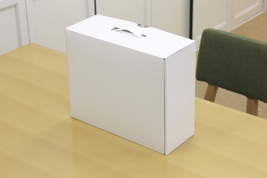
To start the assembling process. The actual retail box will be color printed beautiful box.
If you have Ni-MH batteris, start charging now. At least five fully-charged batteries will be needed later. On average, it only takes 30-45 minutes to get to step #53.
|
|---|---|---|
| 2 |
|
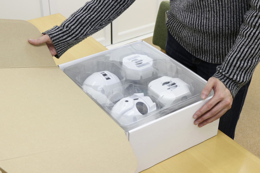
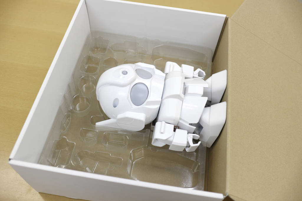
Inside the box, you will find all the parts inside.
Do not throw away this box. It can be used as a:
|
| 3 |
|
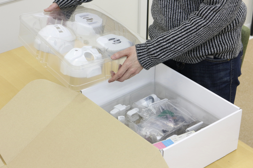
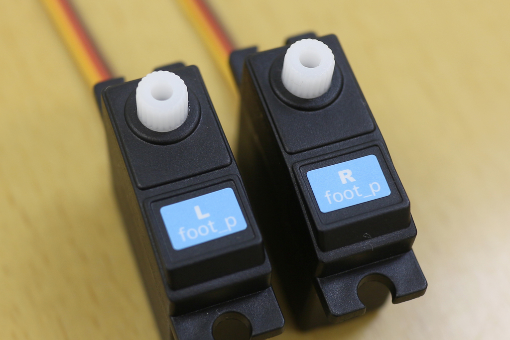
Don't forget the parts on the lower plate. |
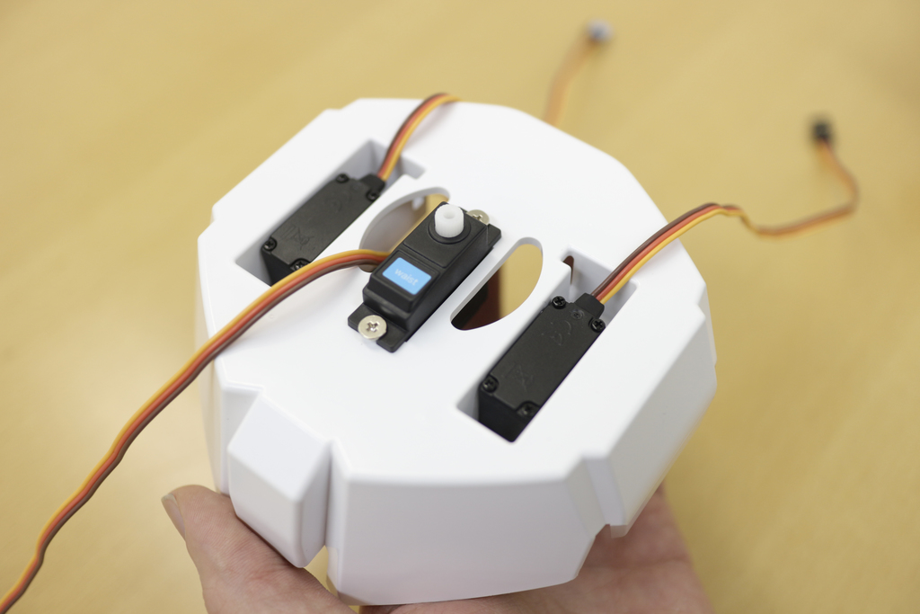
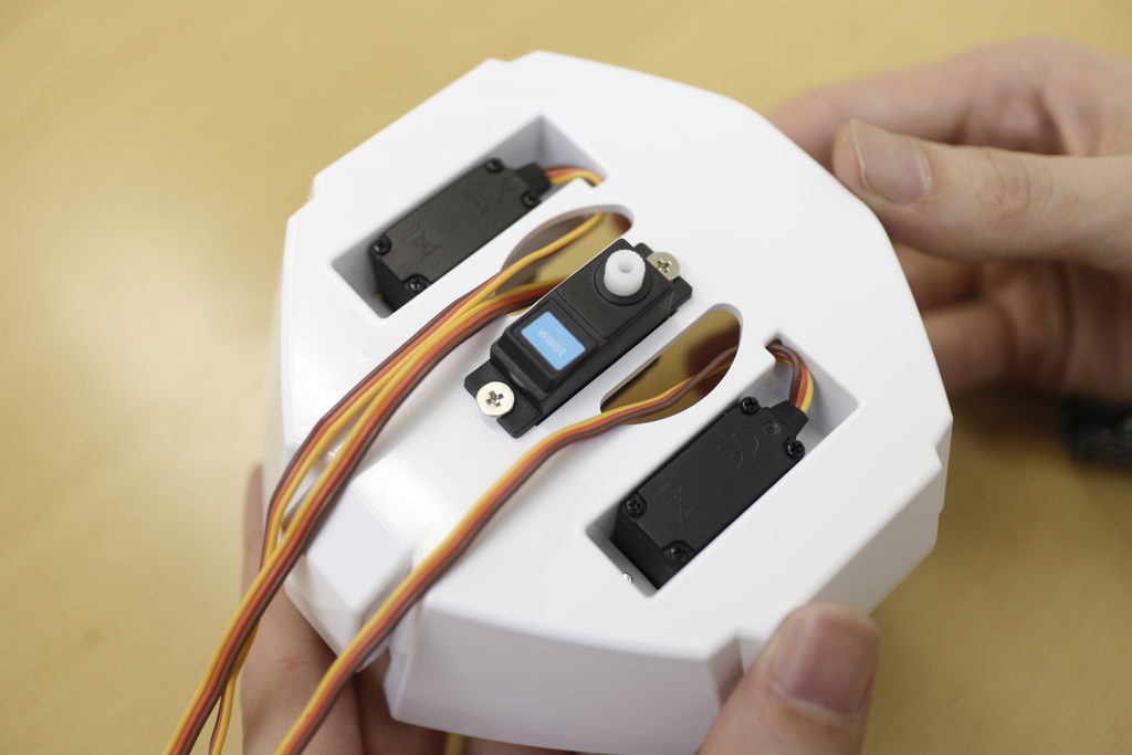
| 4 |

|
Now, unbox all the parts. |
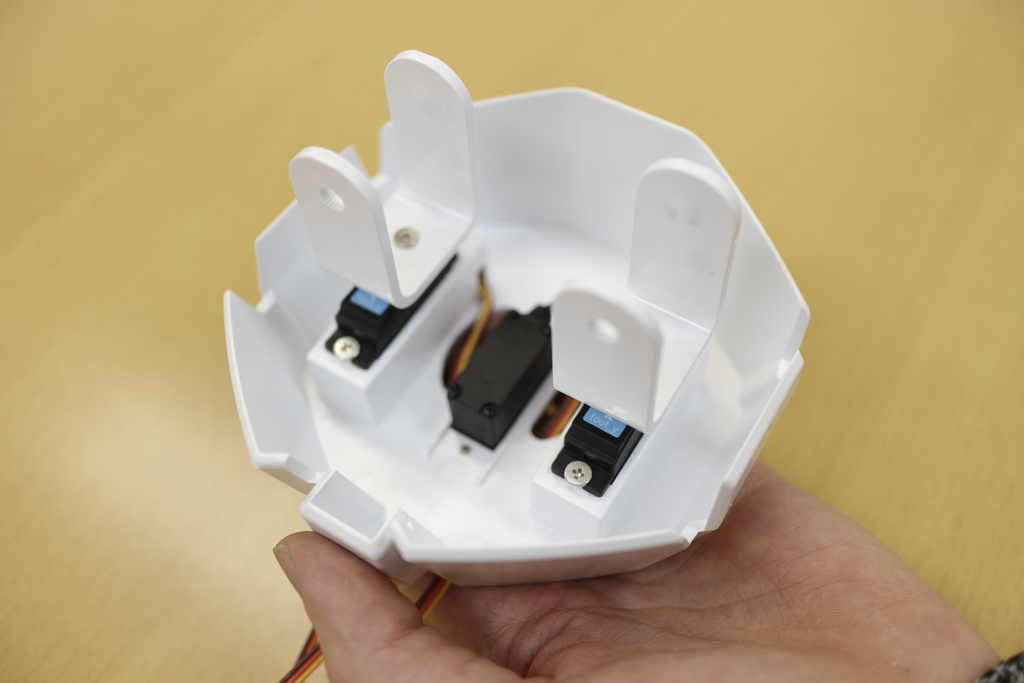
| 5 |

|
Spread the parts so that you can check them easily. Parts List |
| 6 |

|
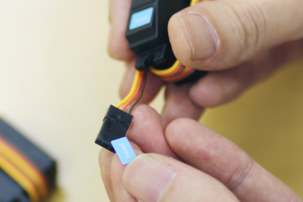
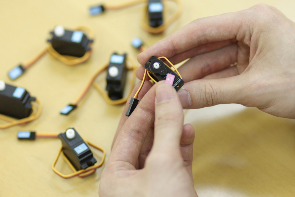
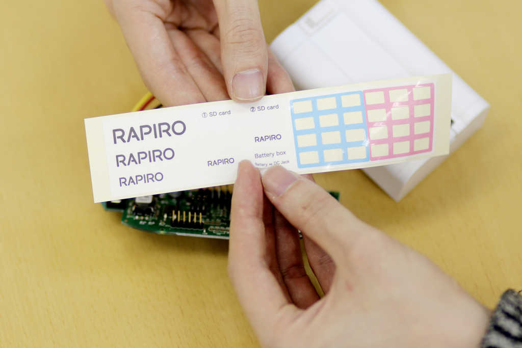
Stick the stickers onto the 12 servo motors. |
| 7 |

|
Blue stickers are for large servo motors (6 pieces). |
| 8 |

|
|
| 9 |

|
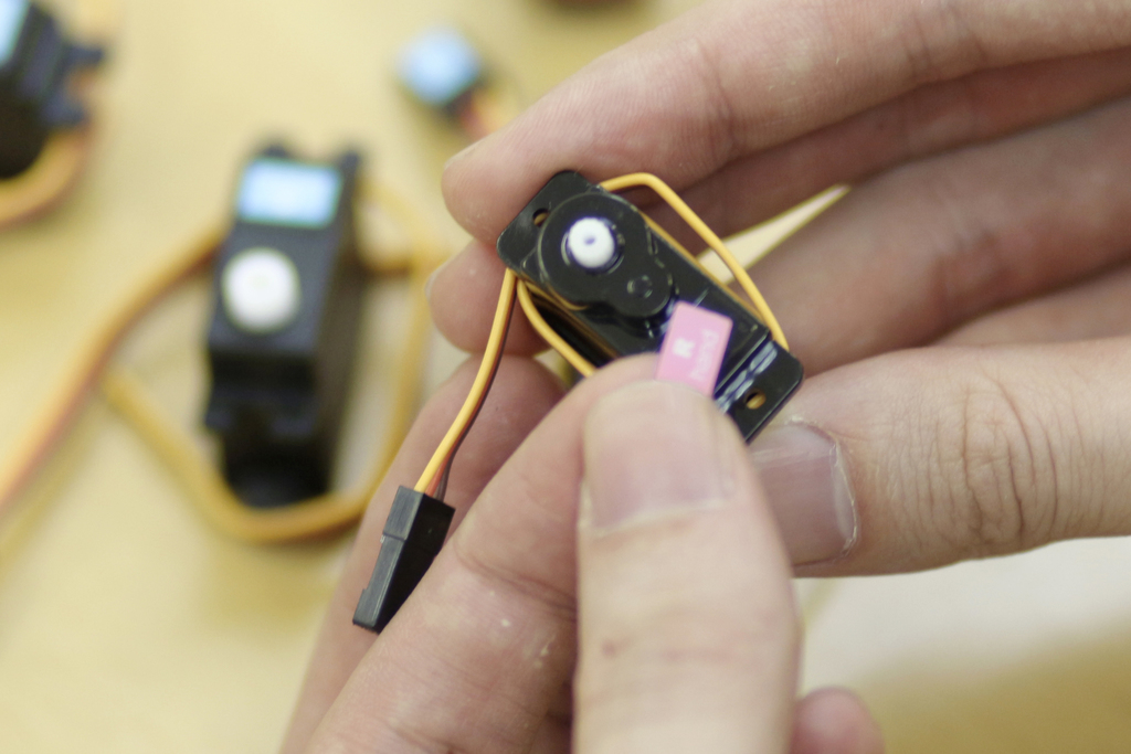
There are two pieces of sticker with same label. Stick them on the main unit of a servo motor and the other on its connector. |
| 10 |
|
|
| 11 |
|
Pink stickers are for small servo motors (6 pieces). |
| 12 |
|
|
| 13 |

|
Repeat the instruction given in Step #9. |
| 14 |

|
|
| 15 |

|
It'll serve as a helpful mark to distinguish connect board and servo motors. |
| 16 |
|
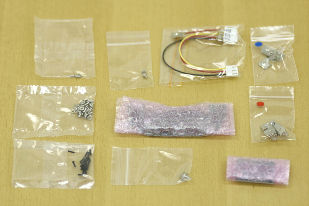
These are contents of the other resealable bag. |
| 17 |
|
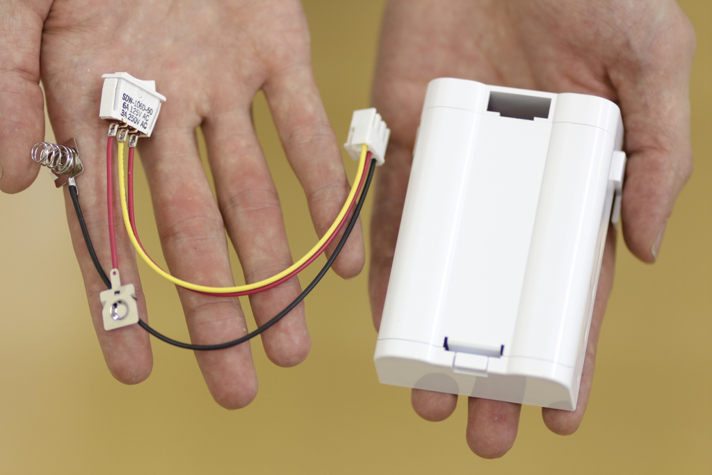
Next step is to assemble the battery box. |
| 18 |

|
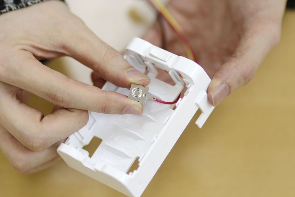
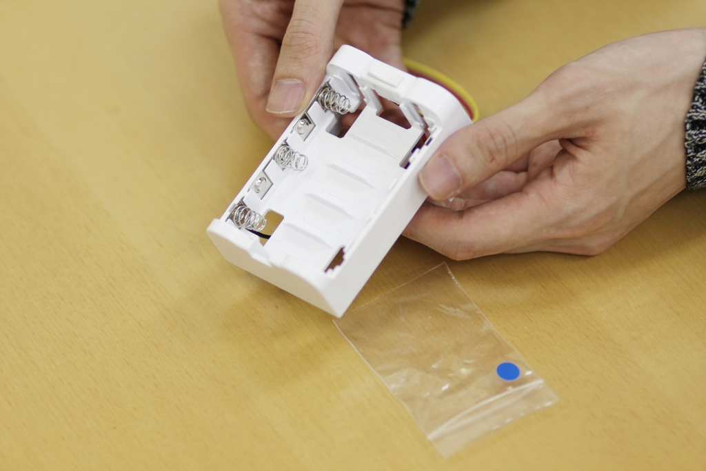
Open the cover of battery box, then pass the connector through the hole of battery box as shown the photo. Once that is done, attach the switch cable on. |
| 19 |

|
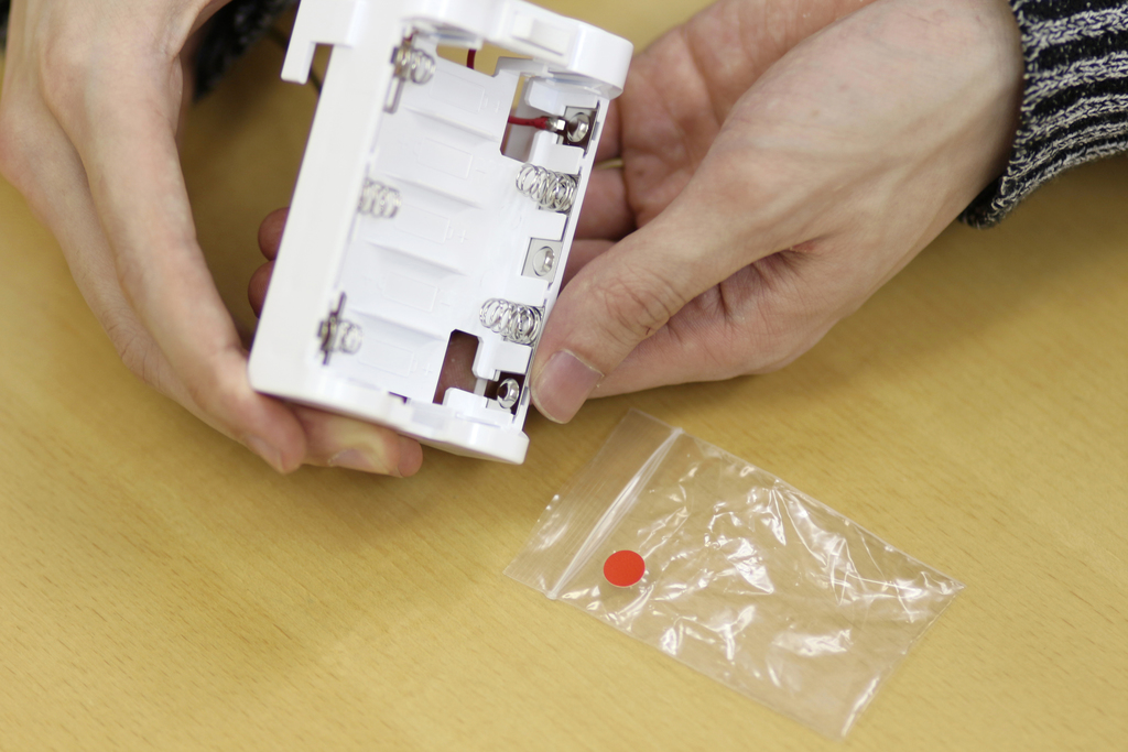
Insert the 3-pin plug into the hole of the battery box from the inner side to the outer side. |
| 20 |

|
Insert battery contacts into the hole of the battery box with the 3-pin plug. |
| 21 |

|
Insert all cables into the hole of battery box, as shown in the photo. |
| 22 |

|
Insert the switch in the same direction as the photo. |
| 23 |

|
Insert battery contact in the hole toward inner side from outer side. |
| 24 |
|
|
| 25 |

|
Insert the battery contact into the slot of the battery box. |
| 26 |

|
Insert the battery contact firmly. |
| 27 |

|
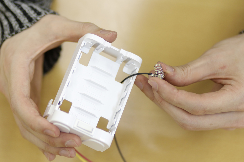
Next, Insert another battery contact into the hole, as shown in the photo. |
| 28 |
|
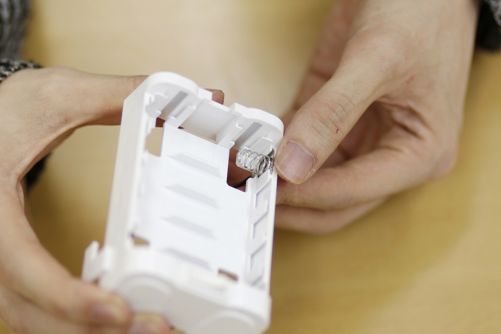
Insert another battery contact with a spring into a hole at diagonally opposite corner. |
| 29 |

|
Insert the battery contact into the slot of the battery box. |
| 30 |
|
Insert the battery contact firmly. |
| 31 |
|
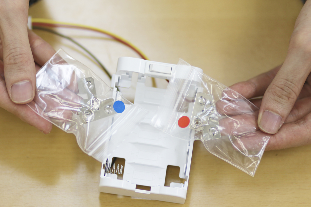
Attach battery contacts to the battery box. Battery contacts are in resealable plastic bags marked with blue and red stickers. |
| 32 |

|
Unpack the bag marked with a blue sticker. Insert the battery contacts to the left side, where you already have a battery contacts with spring inserted. |
| 33 |

|
There are two battery contacts in the bag. This picture is when inserting the first one. |
| 34 |
|
Insert the second battery contact here. |
| 35 |

|
Insert the battery contacts firmly. |
| 36 |

|
Unpack the bag marked with a red sticker. Insert the battery contacts to the right side. There are two battery contacts in the bag. This picture is when inserting the first one. |
| 37 |

|
Closeup picture inserting the first battery contact from the bag with a red sticker. |
| 38 |
|
Insert the battery contacts firmly. |
| 39 |
|
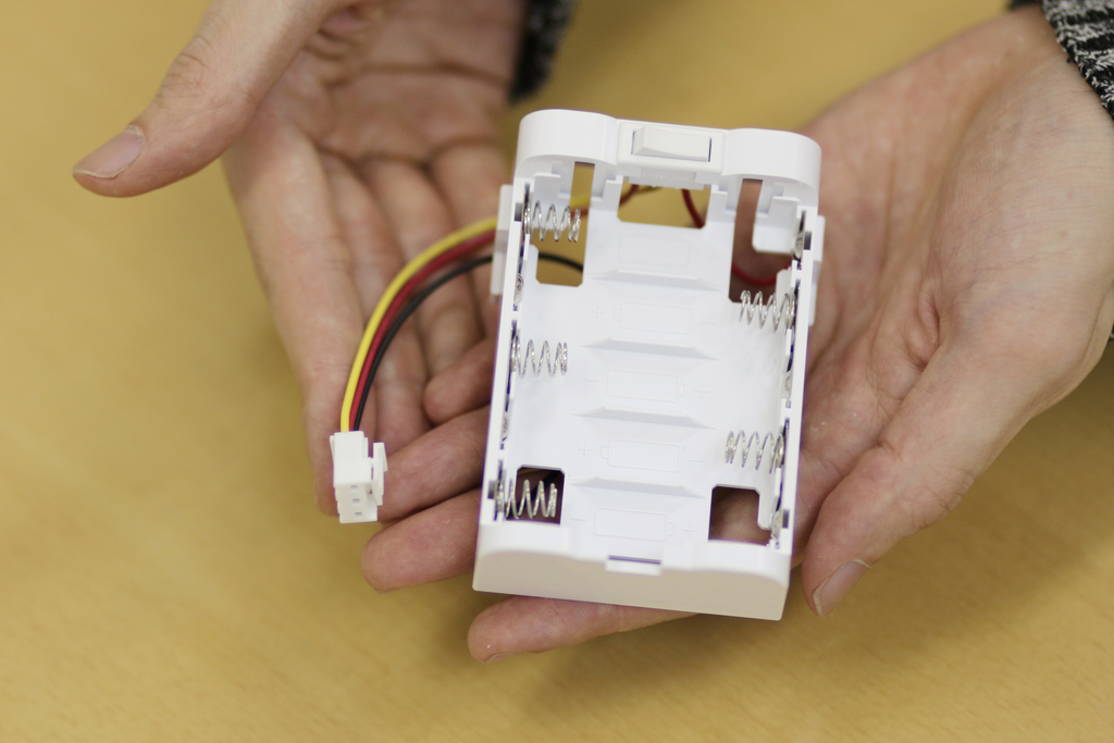
Completed battery box looks like this. Please note that the spring locations alternate left and right. |
| 40 |

|
You may want to push the red cable inside the battery box so that the cable will not run out. |
| 41 |

|
Make the battery cables to be routed along with the back surface of the battery box. |
| 42 |

|
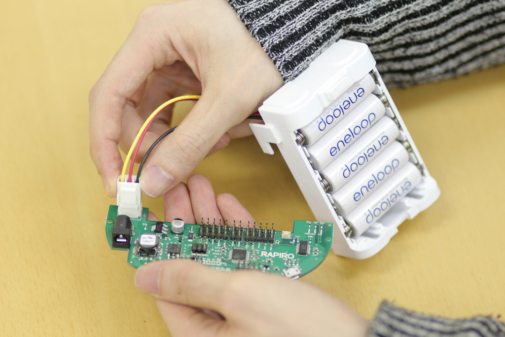
Use Five AA Ni-MH batteries which must be one of these. IMPORTANT Before you insert AA Batteries, make sure right-side of the switch is pushed. |
| 43 |

|
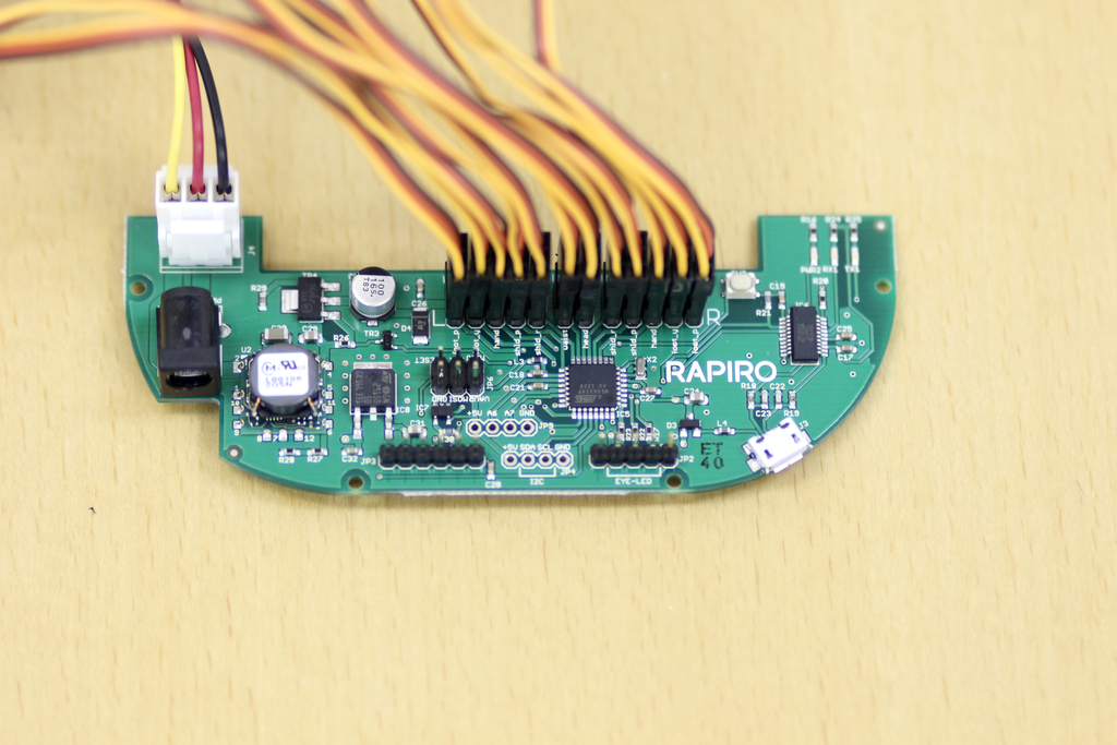
Next, take the RAPIRO boards. |
| 44 |
|
Insert the connector of battery box into the RAPIRO board, as shown in the picture. |
| 45 |

|
Close the cover of battery box. |
| 46 |
|
Paste this sticker on a cover of battery box. |
| 47 |

|
Paste the sticker under the switch. |
| 48 |

|
Like this. |
| 49 |
|
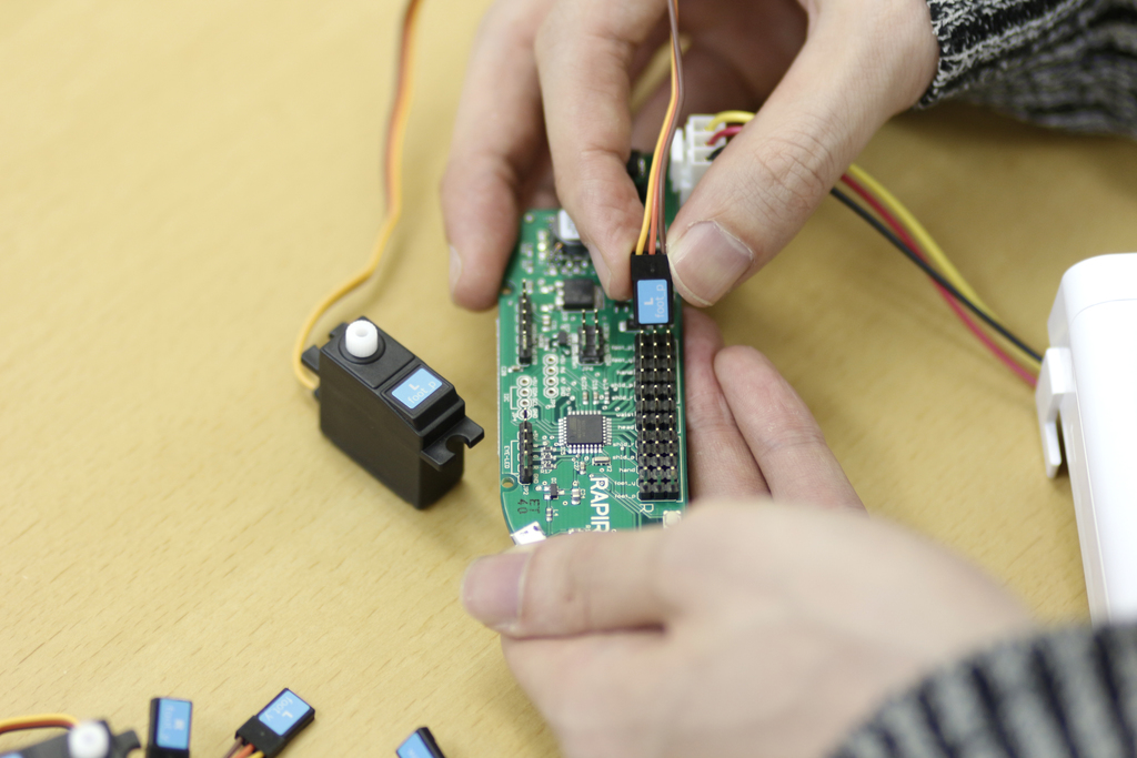
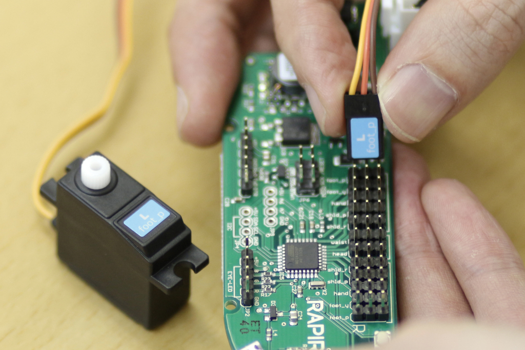
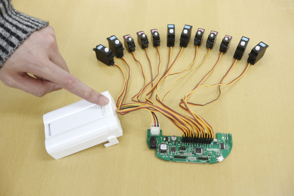
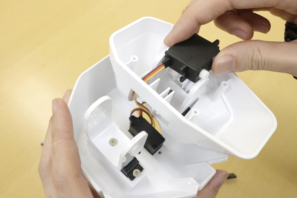
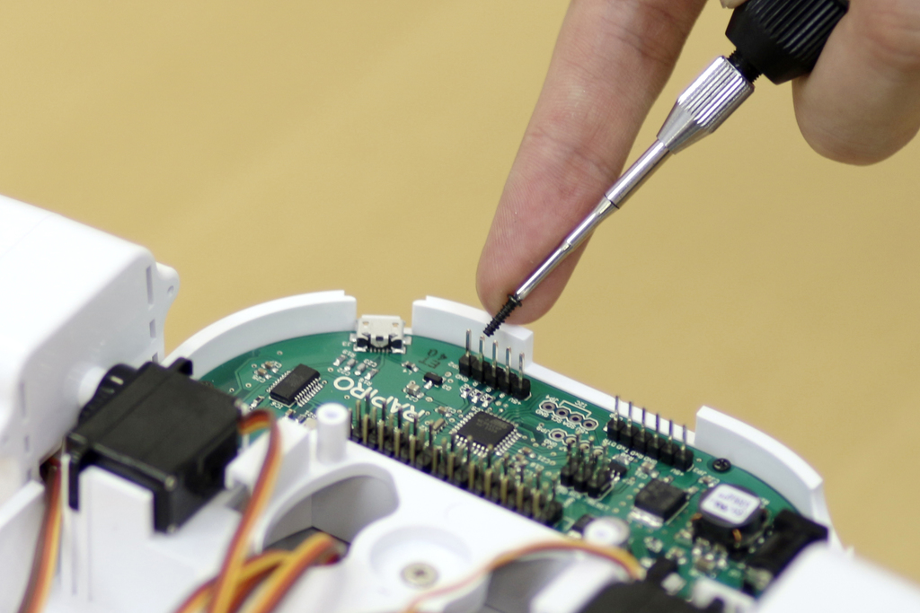
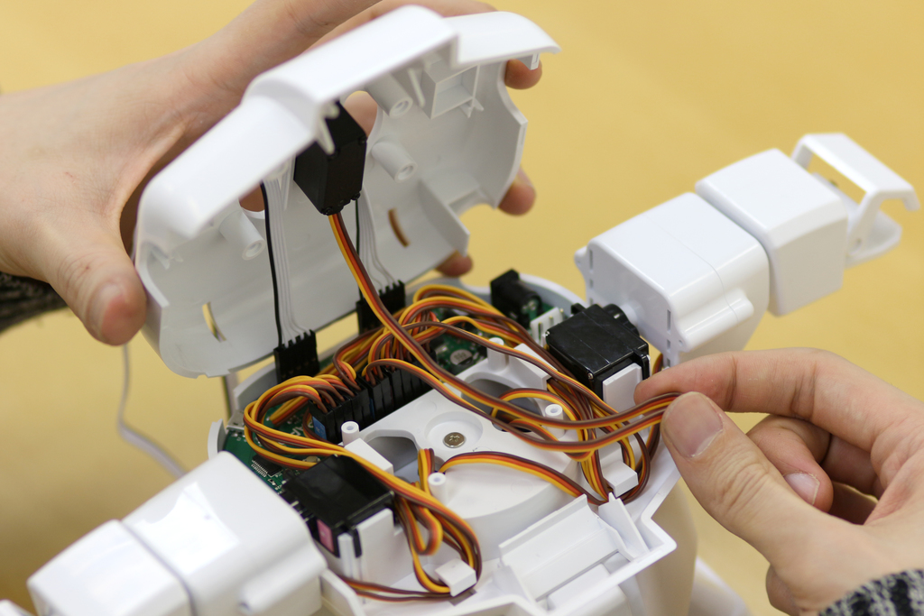
Insert servo connectors which corresponded to pins. Pin names are written on the board. Pins' order from top to bottom are: Right: foot_p, foot_y, hand, shld_p, shld_r Center: head, waist Left: shld_r, shld_p, hand, foot_y, foot_p |
| 50 |
|
When attaching connector to the pin, the yellow cord should be on the left with orange in the middle and brown cord should be on the right. Repeat the procedure until all the connector is on the pins. |
| 51 |
|
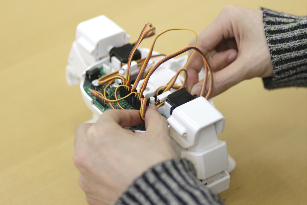
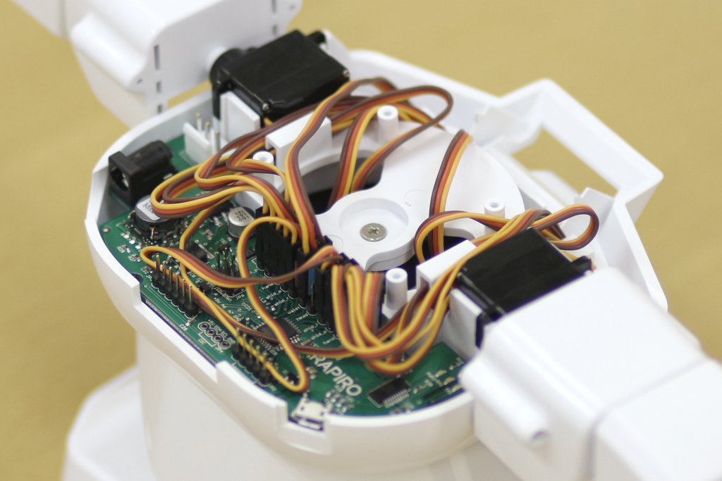
Insert all servo connectors to pins on board. At that time, be careful not to make a mistake of confusion between "R" and "L". |
| 52 |

|
If your batteries are still charging, please take a break. Five batteries must be fully-charged before moving onto the next steps.
|
| 53 |
|
Please turn on the switch (push left-side of the switch) to make Initial adjustment of servo angles. All servo axes are rotated to initial angles. IMPORTANT Please use fully charged five Ni-MH batteries. If the charging of batteries is incomplete, servos does not work correctly with noise. IMPORTANT It's very important that you must maintain servo motor's initial position while you assemble. After you initialize servo motors along with this step, you MUST NOT change the angle of the servo motors until you complete assembly. This means you must be very careful about keeping its angle when you assemble parts around servos. Wrong angle is one of the common reasons why Rapiro goes crazy when you put the power on. |
| 54 |

|
Wait few seconds until all the servo-motors are stabilized. You are all set if you do not hear any noise or see any movement of the servo-motors. Turn the power off and remove all the connectors from the pins. |
| 55 |

|
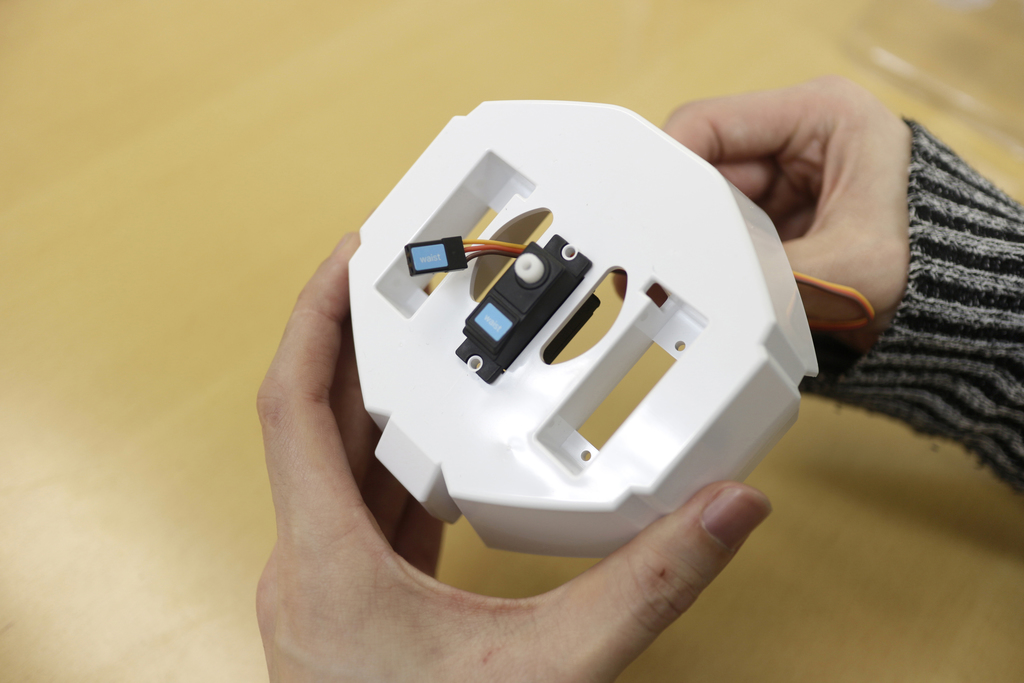
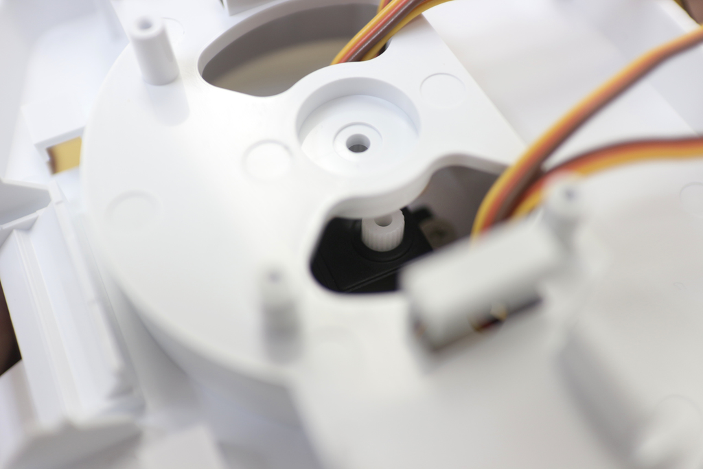
Insert the cable and the waist servo into the square hole of the waist part from upside to down side. |
| 56 |
|
Then insert the cable in a side hole from downside to upside. |
| 57 |

|
Tighten the waist servo with silver screws (Tapping 3mm). |
| 58 |

|
Silver screws (Tapping 3mm). |
| 59 |

|
Tighten the waist servo with silver screws (Tapping 3mm). Be careful to not over tighten. |
| 60 |

|
Tighten other side. |
| 61 |
|
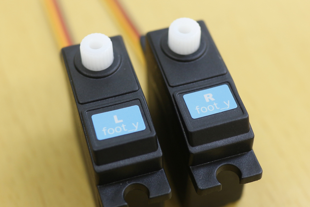
Next, take "R foot_y" and "L foot_y" servos. |
| 62 |

|
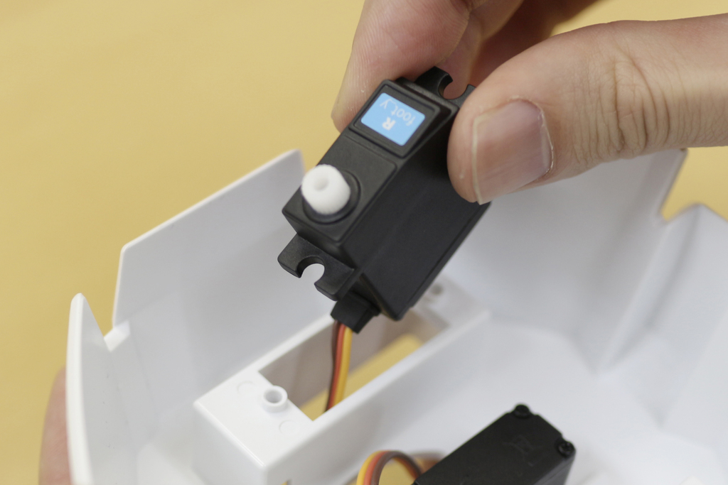
Insert "R foot_y" and "L foot_y" into square holes, which correspond them sides, from downside. |
| 63 |
|
|
| 64 |

|
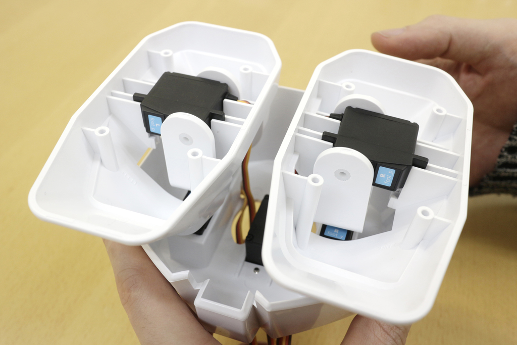
Confirm servo directions and sides. |
| 65 |

|
Tighten servos with silver screws (Tapping 3mm). Be careful to not over tighten. |
| 66 |
|
When you are finished tighten the screw, turn over the servos. |
| 67 |

|
Pass through the cable into the slit, as shown in the picture. |
| 68 |

|
Both of cables was passed through into the slits, like this! |
| 69 |

|
Pass through the cable further into the next hole. |
| 70 |
|
When you finished through the both of cables, look like this. |
| 71 |

|
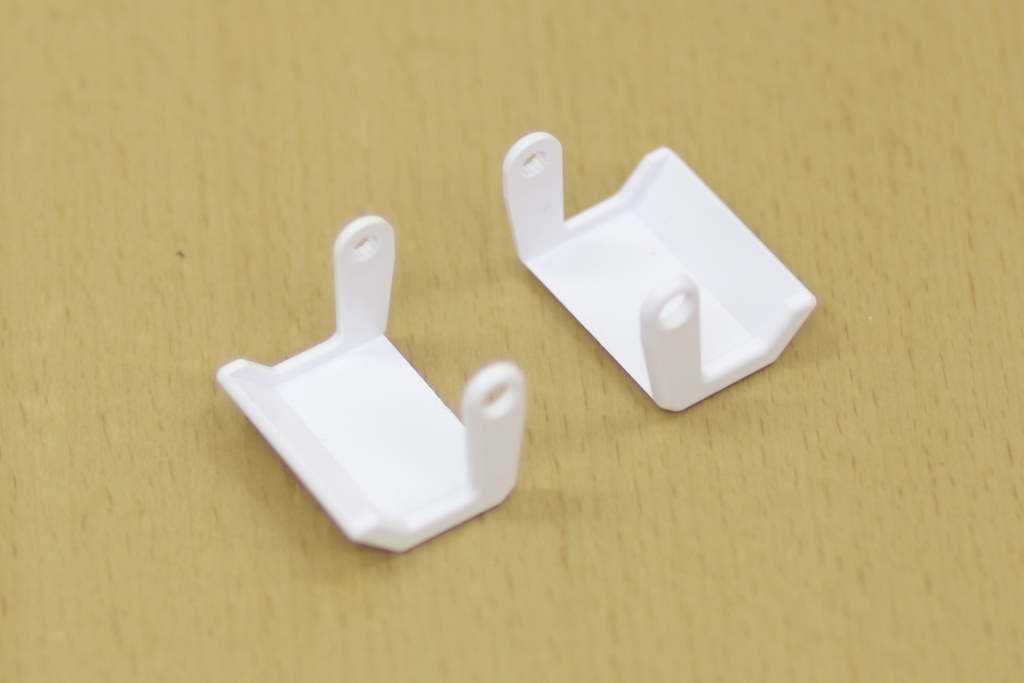
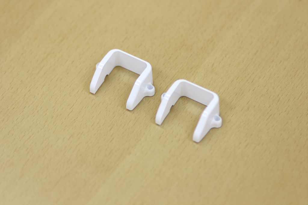
Next, use the part that has a U-shape. |
| 72 |

|
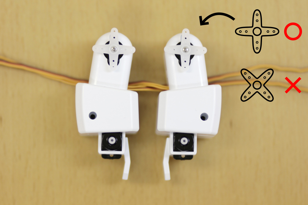
Insert the "R foot_y" and "L foot_y" servos shaft inside the U-shaped parts. Don't turn the shaft of the servos, because it's in the initial value of the angle. There are individual differences in the initial value of the servo motor, so sometimes it might not be completely parallel. But don't panic! It can be adjusted in the program at the end. |
| 73 |

|
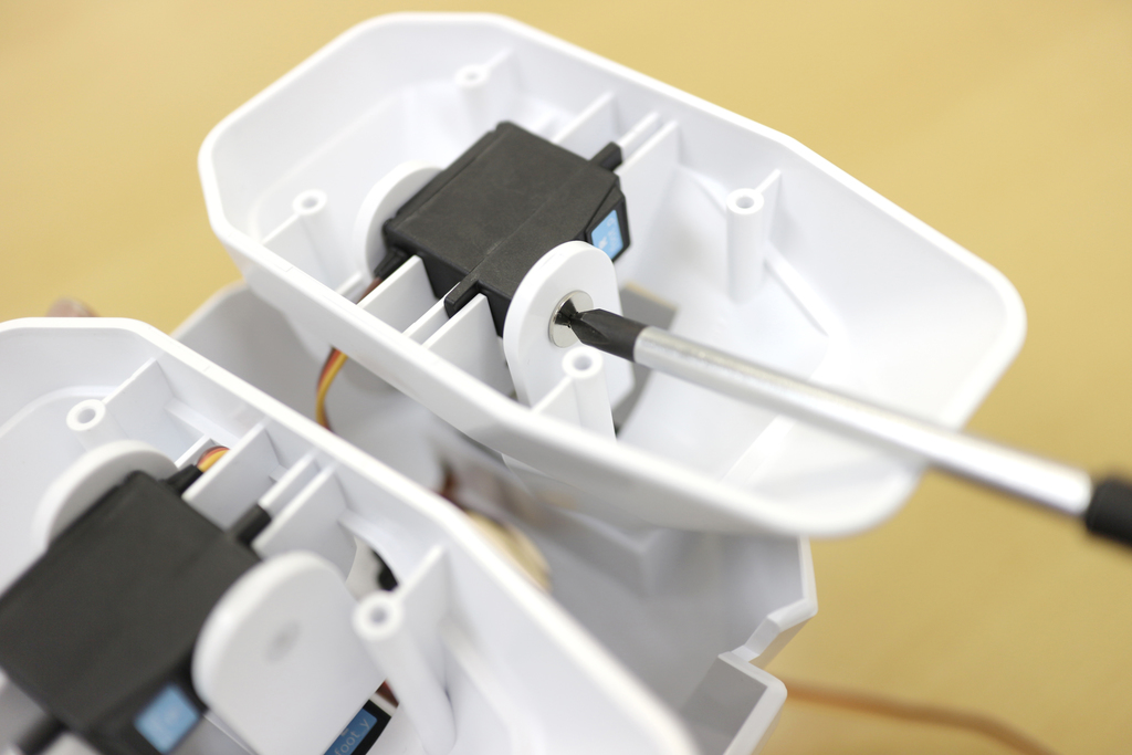
Tighten the servos with the silver screws (Tapping 3mm). |
| 74 |
|
It should look like this. |
| 75 |

|
Next, Use the right foot part. Be careful to not mistake the "right side" or "left side", when you assemble. |
| 76 |

|
Combine the right foot part and U-shaped part as shown. |
| 77 |

|
It should look like this. It has not been fixed yet. But the placement as shown will be okay. |
| 78 |
|
Next, fix the both of foot parts by using "R foot_p" and "L foot_p". |
| 79 |

|
Pass through the cable into the waist parts first. Then as shown, pass through from the foot parts to the waist parts. |
| 80 |

|
Pass through the cable into the waist parts first. |
| 81 |
|
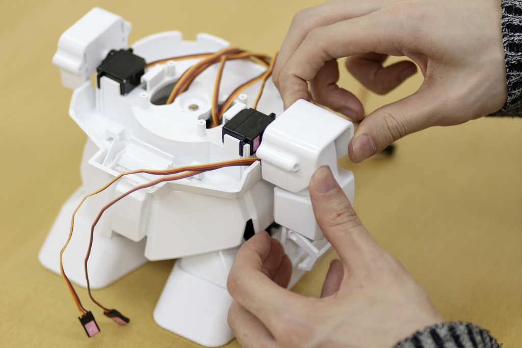
Next, attach the servo motor to the U-shaped parts. Widen the U-shaped parts, then position the servo to be horizontal. |
| 82 |

|
Next, insert the tab of the servos into the slit of the right foot parts, then check their position. |
| 83 |

|
Next, assemble the left foot parts, as the right one. Insert the left foot parts at first, then pass through the cable. |
| 84 |

|
|
| 85 |
|
Looks like this when you attached both of servos. They need to be almost horizontal. |
| 86 |

|
|
| 87 |

|
|
| 88 |
|
Tighten the servos with the screws. |
| 89 |

|
Fixed the servos of foot parts, as shown! |
| 90 |

|
Attach the sole of the foot. Be careful to not mistake the "right" and "left". |
| 91 |

|
Tighten the four places with the silver screws (Tapping 3mm). |
| 92 |

|
Looks like this. |
| 93 |

|
Attach the sole of the foot parts to the other side. |
| 94 |

|
Tighten the four places with the silver screws (Tapping 3mm). |
| 95 |

|
Now we are done assembling the lower body part! The bottom of Rapiro's feet are smooth and could cause it to fall on certain surface. We suggest that the user purchase mousepad and two-sided tape to create Rapiro's footpad. You will need to cut the mousepad to fit the foot of Rapiro. When attaching the mousepad to Rapiro's feet, the smoother surface should be taped to the feet and the rubbery(bumpy) surface should be touching the floor. |
| 96 |
|
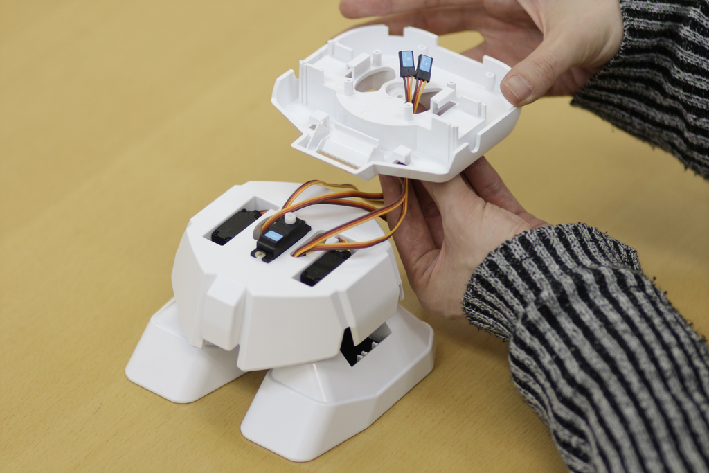
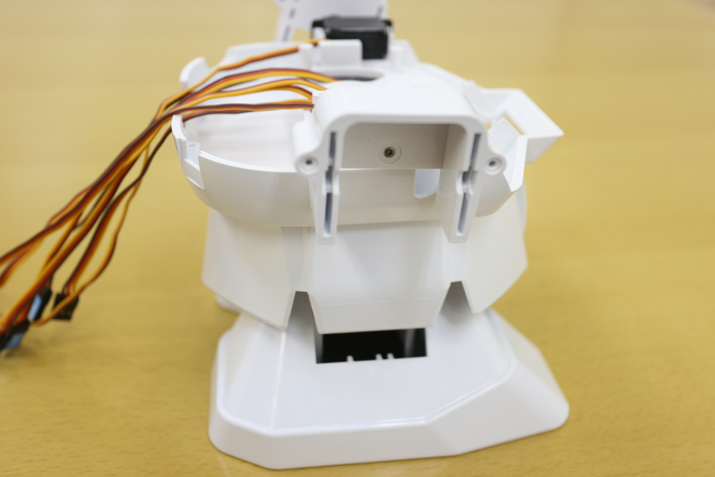
Next, assemble the upper body. The cable which come from the waist parts pass through into the hole of the chest parts. |
| 97 |

|
The five cables pass through to the hole of the chest parts as shown. |
| 98 |
|
|
| 99 |

|
Tighten the servos with the silver screws (Tapping 3mm). |
| 100 |

|
|
| 101 |

|
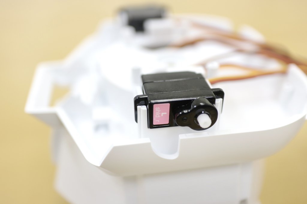
In the arm parts, use the small servos. Attach "R shld_r" and "L shld_r". |
| 102 |
|
|
| 103 |

|
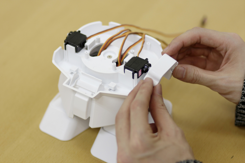
These are the shoulder parts. |
| 104 |
|
|
| 105 |

|
Servos have a slight individual differences of initial angles.Therefore, you may be not able to install shoulder parts horizontally. In such a case, you can install the shoulder part to be a roughly horizontal angle. And if anything, You should install shoulder parts to be inclined behind its back. So, you can make adjustments by program via Arduino IDE later. |
| 106 |

|
Use the thinner silver screws (Tapping 2-5mm). |
| 107 |

|
|
| 108 |

|
|
| 109 |
|
|
| 110 |

|
For next steps, we will be using the four small servos and the arm parts. |
| 111 |

|
|
| 112 |

|
Assemble the right arm first. Let the cable to extend along the back of the servos, as shown. |
| 113 |

|
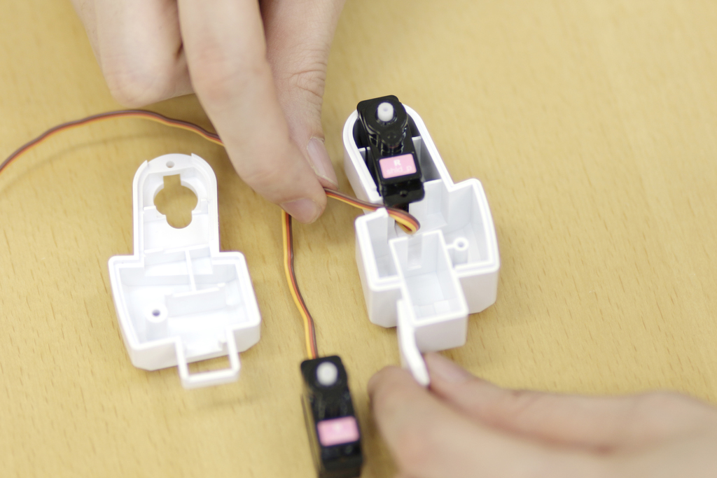
Keep the shape of the cable, then insert "R shld_p" to the side of the shoulder of the right arm part. |
| 114 |
|
Wire the cable from the slit to the outside, after attaching "R shld_p". |
| 115 |

|
Next, let the cable of "R hand" to extend along the back of the servos, as shown. |
| 116 |

|
Keep the shape of the cable, then insert "R hand" to another side of the arm part. |
| 117 |

|
Wire the cable from the slit to the outside, same as the "R shld p" |
| 118 |

|
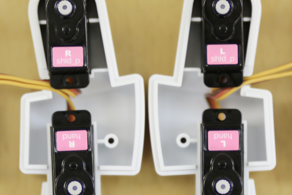
Assemble the left part, as the right part. |
| 119 |
|
Look at the picture carefully, check the placement of each servo. |
| 120 |

|
Cover the arm parts, as shown. |
| 121 |

|
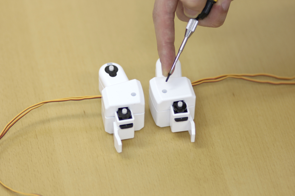
For fixing the arm parts in place, use the thin black screws(Tapping 2-7mm). |
| 122 |
|
Insert the black thin screw (Tapping 2-7mm) to the hole of the arm parts. |
| 123 |

|
Tighten the screws. Do not over tighten! |
| 124 |

|
Tighten the hole of the shoulder side as well, with thin black screws (Tapping 2-7mm). |
| 125 |

|
Do not over tighten! |
| 126 |

|
Looks like this. You used the 4 screws. |
| 127 |

|
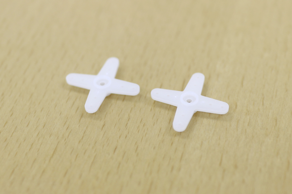
Next, use the cables and the cross parts that are packed in the bag of servos. |
| 128 |
|
The cross parts are first. |
| 129 |

|
Insert the cross parts to the arm parts that you assembled. |
| 130 |

|
Look at the picture carefully, then attach the cross parts as shown. Don't turn the shaft of the servos. |
| 131 |

|
these are the smaller screws again |
| 132 |
|
Looks like this. |
| 133 |
|
These are the finger parts. |
| 134 |

|
Attach the finger parts to the arm parts. The jagged hole of the finger parts should be attached to the side of the shaft. |
| 135 |

|
|
| 136 |

|
|
| 137 |

|
Attach the arm part that you assembled to the shoulder parts. The cross parts should be looking out on the back side of the body. IMPORTANT The cable between the body and the arm should be long enough as shown in Step #174. |
| 138 |

|
Insert the cross parts to the slit of the shoulder parts. |
| 139 |
|
These parts are for the shoulder. |
| 140 |
|
Combine the shoulder parts and the cross parts. |
| 141 |

|
Tighten the parts with the black thin screws (Tapping 2-7mm). |
| 142 |

|
|
| 143 |

|
Attach the RAPIRO board. |
| 144 |

|
|
| 145 |

|
Put the board on the chest parts. |
| 146 |

|
Tighten the 4 places on the board with the thin black screws (Tapping 2-7mm). |
| 147 |
|
|
| 148 |

|
|
| 149 |

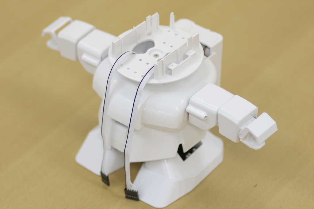
|
Connect the servos that you assembled to the board. |
| 150 |

|
Insert all of the connectors while checking both of the names. (The seal on the connectors, and The terminal name on the board) The yellow cable should be the inner side, and the brown cable should be the out side of the board. |
| 151 |

|
11 cable connectors have been connected to the terminal. (Excluding the head parts) |
| 152 |
|
|
| 153 |

|
|
| 154 |
|
|
| 155 |

|
|
| 156 |

|
|
| 157 |
|
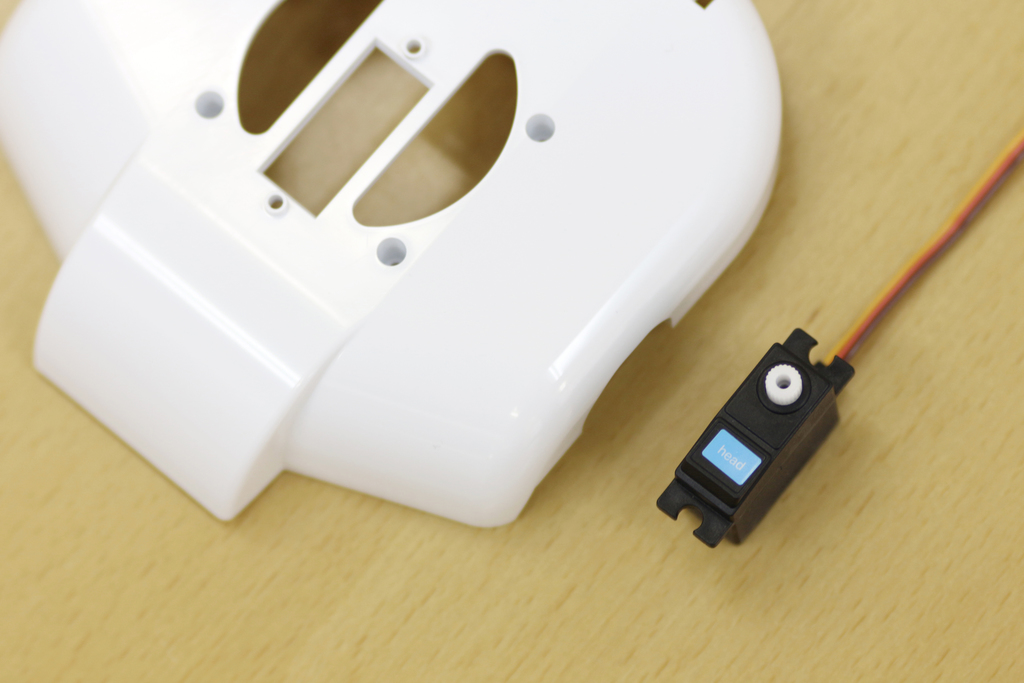
In the end, attach the servo for "head". |
| 158 |

|
|
| 159 |

|
Pass through the cable to the square hole in the center of the cover of the chest parts. |
| 160 |

|
|
| 161 |

|
Tighten the thick silver screws (Tapping 3mm). |
| 162 |

|
Do not over tighten! |
| 163 |

|
You need to tighten at the two points. |
| 164 |

|
Connect the "Head" connector to the main board. 6th from the right. |
| 165 |

|
Insert the 5-pin cable into the right (RAPIRO's view) hole of the breast part. |
| 166 |

|
Pull the 5-pin cable through the right hole. |
| 167 |

|
Insert the 6-pin cable into the left (RAPIRO's view) hole of the breast part. |
| 168 |
|
Route the "Head" cable not to be caught in the body parts. |
| 169 |

|
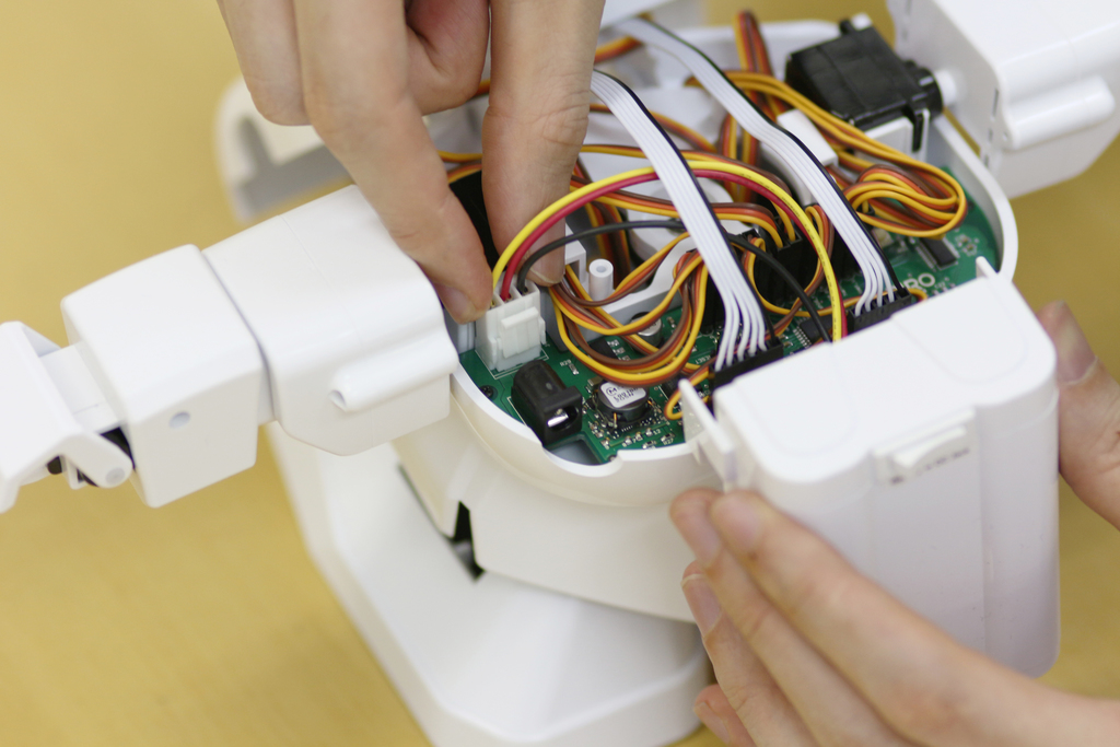
Connect the battery connector to the main board before closing the body parts. |
| 170 |

|
The battery cable should go through between the 6-pin cable and 5-pin cable. |
| 171 |
|
Connect the battery connector to the main board. |
| 172 |
|
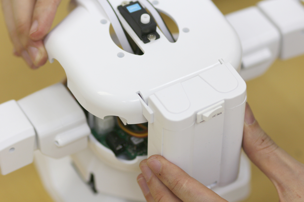
Move the breast part just over the body, and hook the battery box to the slits on the breast part. |
| 173 |

|
Secure the battery box using a silver tapping screw (3mm). Please note that you don't have to fully screw in the hole, stop screwing at the depth as shown in the picture. |
| 174 |

|
Close the breast part on the body parts. The cable between the body and the arm should be long enough as shown in the picture. |
| 175 |

|
This cable should be long enough to move the arm freely. |
| 176 |

|
Screw the breast part on the body parts with four black tapping screw (2mm by 7mm long). |
| 177 |

|
If there is a gap between the breast part and the body part, some cables should be caught in the parts. Remove the breast part and check the cables. |
| 178 |

|
If no cables are caught in the parts, there should be no gap between the parts. |
| 179 |
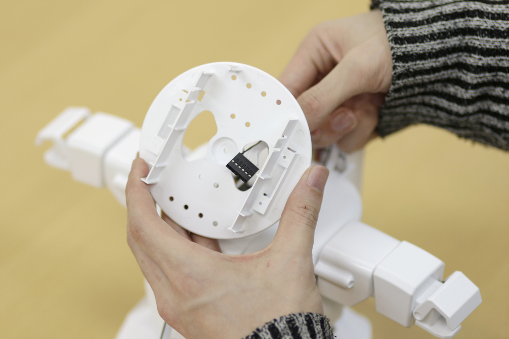
|
|
| 180 |

|
|
| 181 |

|
|
| 182 |

|
Tighten the shaft with the thick silver screws (Tapping 3mm). |
| 183 |
|
The end result will look like this. |
| 184 |

|
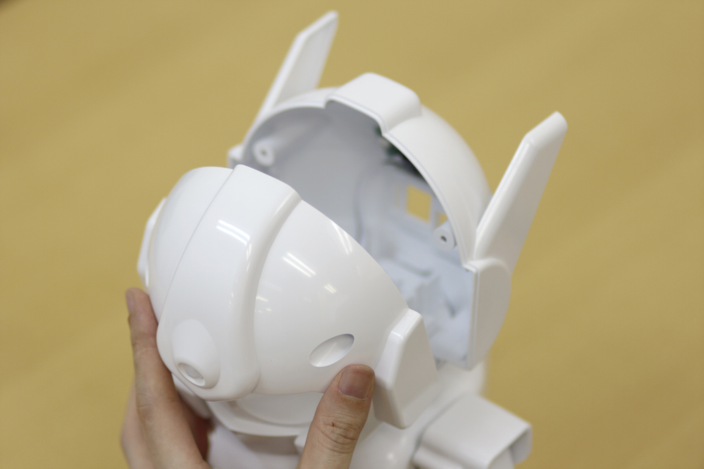
Next, assemble the face. |
| 185 |

|
Insert the ears parts to the back of head. |
| 186 |

|
Insert until you could hear the click sound. |
| 187 |
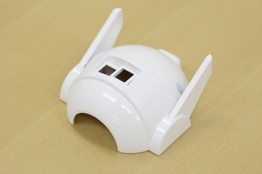
|
It'll look like this when you finished inserting both of ears parts. |
| 188 |

|
Tighten the LED board with screws to the inside of the back of head parts. Use the thick silver screws (Tapping 3mm). |
| 189 |

|
Do not over tighten. |
| 190 |

|
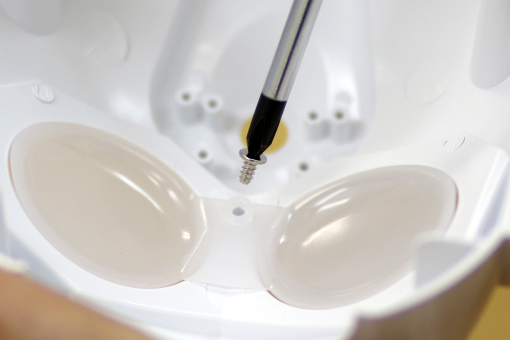
Set the eyes part to the inside of the face. |
| 191 |

|
Tighten the inside of middle forehead with the thick silver screws (Tapping 3mm). Do not over tighten. |
| 192 |
|
Tighten the inside of middle forehead with the thick silver screws (Tapping 3mm). Do not over tighten. |
| 193 |

|
|
| 194 |

|
|
| 195 |
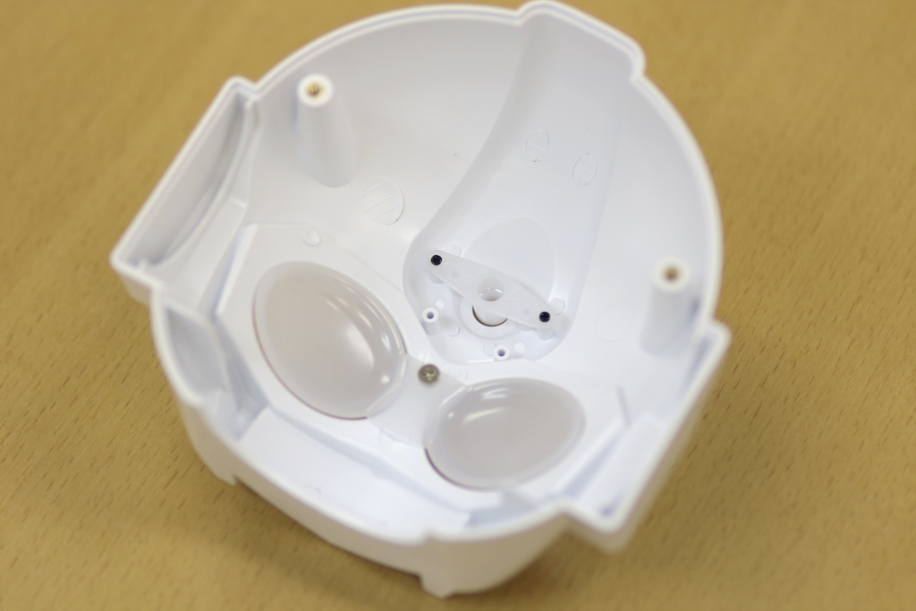
|
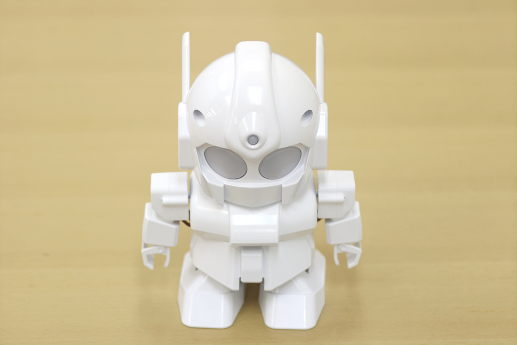
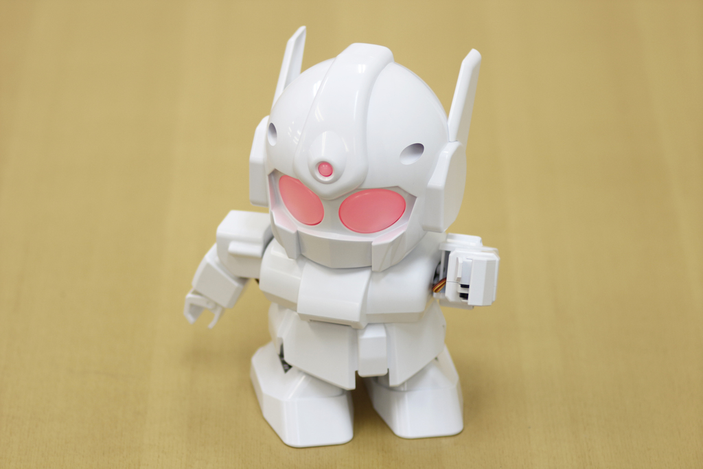
The face parts is now completed! |
| 196 |

|
|
| 197 |

|
|
| 198 |
|
|
| 199 |

|
Use the flat head screws for the head parts. the screws (M3) are only two pieces in this kit. |
| 200 |

|
Tighten the flat head screw from the back of head. |
| 201 |

|
|
| 202 |

|
|
| 203 |
|
|
| 204 |

|
For the final process, connect the computer, and adjust the value of the angle due to individual differences of the servos. Note: If you hear large buzzing sounds from servo motors when Rapiro stands with power supply, it's mostly because of the reason that the initial angle of servo motor on foot is not horizontal enough. In this case you can adjust the angle by folloing process so that the buzzing sounds will be ceased. You are better to be careful especially for foot servo motor adjustment, because servo motors are not durable under strain by inproper adjustment. You need to install these softwares, if you haven't already. Arduino IDE FTDI Drivers ( How to install.) Download the sketch from the URL below and open it with Arduino IDE. Standard firmware for controller board (Arduino sketch) [download] |
| 205 |

|
The eye piece will light up when you connect the computer and RAPIRO with the Micro-USB cable, and turn on the switch to energize to the servos as shown. |
| 206 |

|
If the arms or legs are inclined a bit when you turn on the switch, |
| 207 |

|
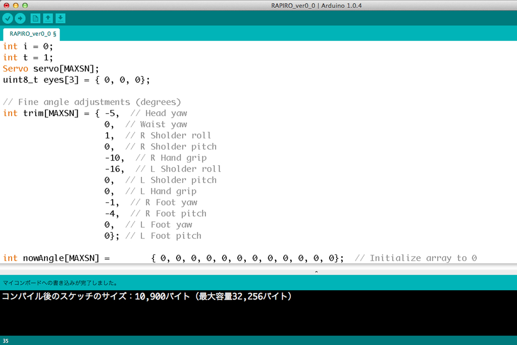
Enter the correction value of the angle to the array of int trim[MAXSN] |
| 208 |
|
Change the correction value of the servos that are inclined, then upload the standard firmware for controller board to the RAPIRO board. Select "Arduino Uno" from tool menu when you upload the sketch. |
| 209 |

|
Repeat the changing the array of int trim[MAXSN], and the uploading its sketch, until the posture is fixed. |
| 210 |
|
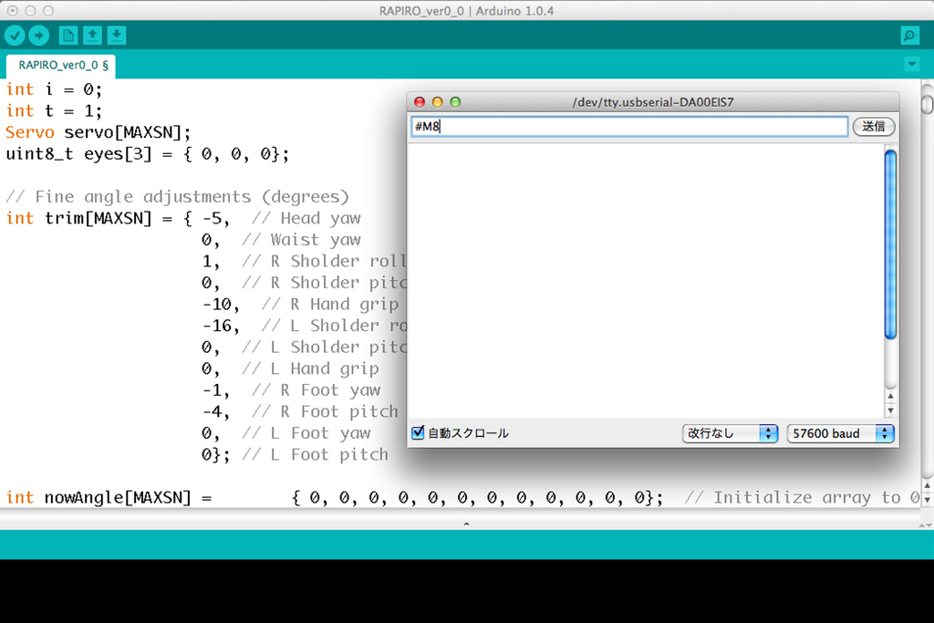
When you have made adjustments of servos, let's send Serial Command #M1- #M9 via serial terminal of Arduino IDE. Then RAPIRO will make the motion which is assigned to the command number. Serial Commands List |
| 211 |
|
If you put Rasberry Pi and/or wireless communication module into RAPIRO and program them, you will be able to control RAPIRO wirelessly. Please refer to the raspberrypi_EN.txt for complete installation of Rapiro setup to your Raspberry Pi2. You can find an additional assembly instruction for Raspberry Pi2 after the setup. Adapter Kit for Raspberry Pi2 |
| 212 |
|
One of the two cushioning tray can be used to secure the assembled RAPIRO in the box. |
| 213 |

|
The box can be used for storage, and to bring out. |
|
If you've purchased Rapiro from us, you can download these for FREE!
|
||
You may be interested
|
Remote Control |
Security Robot |
|
Don't trust this video. It's impossible. |
The video you can trust. |